You might have scratched your head and said, “OMG!! Its difficult to interface MSP430 and LCD!” If you have been working on it then you surely would have! Also here in today’s blog I would like to add another solution too. I keep hearing that msp430 cannot be used as atmega. Whenever asked the reason what people say is that the logic level doesnt match. One is in cmos and other is in ttl. Well, one should agree the point that we hobby project makers are always a long way behind the companies. That is the main reason in which we dont employ mcu as msp430 which is small and but highly powerful. In my previous post I had shared my experience with TI ADC Phase 1. I had used msp430f149 for my project and I had faced similar problems “logic mismatch”. So today what I am writing will be concentrated on how to solve this problem. My team has found a good solution to solve this issue.
Before coming to solution its always required to know what exactly the problem is. Let me give an example and explain the problem.
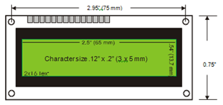
The most important problem everyone has is LCD 16×2 interfacing with MSP430. The LCD 16×2 which is usually available in market works on TTL logic. Now what is TTL logic is?
As wiki says, “Transistor–transistor logic (TTL) is a class of digital circuits built from bipolar junction transistors (BJT) and resistors. It is called transistor–transistor logic because both the logic gating function (e.g., AND) and the amplifying function are performed by transistors (contrast with RTL and DTL). Standard TTL circuits operate with a 5-volt power supply. A TTL input signal is defined as “low” when between 0V and 0.8V with respect to the ground terminal, and “high” when between 2.2V and 5V(precise logic levels vary slightly between sub-types and by temperature). TTL outputs are typically restricted to narrower limits of between 0V and 0.4V for a “low” and between 2.6V and 5V for a “high”, providing 0.4V of noise immunity”
It should be noted that, though TTL has logic low as <0.8V and high as >2.6V many a times the actual value will be low as <1.5V and high as >3.5V.
Now coming to CMOS logic, What is it mean? These logic devices works with 3.3Vpower supply. Here usually low means <0.8V and high means >2.3V.
Observing TTL and CMOS, if ideal cases are considered then there is no trouble in conversion between the two logic levels. 3.3V will be considered as high in TTL. But problem is that ideal case doesnt exit!
So it is much required to do the conversion to get rid of this problem. Hence from many months a lot of work in this part has gone and few possible solution where done. Few among them are mentioned below.
-
Using pull up resistor : Well some people claim this is one of the best and easy solution for this problem. However when comes to LCD interfacing this just doesnt work!
-
Transistor conversion : Using a BJT or MOSFET people say it is possible to convert. Theoretically one can prove this. There are people who have done circuits based on this and solved the LCD problem. However its is that fast and it usually become clumsy.
-
Use another controller : This is one also possible but you need to integrate two controllers. One working in 5V logic and other in 3.3V. Example is MSP430 and ATMEGA. Connect LCD to atmega. This has one main problem that you require another controller! So what is the point of using MSP then? For testing purpose one can use it but when comes to hardware this just complicates the overall thing!
-
Therefore, it was much required to see whether there is any IC which can solve this problem. However, if you search in google you do get a lot of ICs which solves this problem, but there are only few which actually solves! Others have problem of gate delays and frequency matching. Hence a proper IC has to be selected. The IC which I and my teammates found providing the best solution was CD 4050. TI provides this IC too! Use this IC to match the logic levels.
Now let me concentrate mainly on LCD solution and explain in more detail. For any other logic mismatch you just have to change the LCD with your required device 🙂 Thats all!
The main reasons for not working of LCD interface in MSP430 is –
1)LCD (16 x 2) display works with 5V logic level (TTL), where as TI MCU works with 3V logic levels (CMOS). There is voltage level mismatch between the two components.
2) Not understanding data-sheet of LCD 16×2. Contrast pin is not connected properly. LCD which I used datasheet can be seen at http://www.datasheetarchive.com/JHD162A-datasheet.html
3)Initialization problems.
(These were the problems which we faced)
Here are the steps for interfacing TIMCU and LCD (16×2). I have chosen MSP430F149 Micro controller to interface to LCD and have used 8bit logic interface.

Do the connections as you want. However keeping in mind that you do it in sequence. This is will help in easier debugging. In the example provided, I have considered P1 as address/control and P2 as data pins.
Voltage Level mismatch:
To solve the problem of voltage level mismatch between the TIMCU and LCD, as said we will use logic level shifter IC. HCF4050 (or CD4050) from ST electronics. Its a 16 pin IC which converts 3.3V level to 5V level, and 0v to 0v level. These have CMOS hex convertors. The data sheet of IC- HCF4050 can be obtained from the link www.8051projects.info/datasheets/CD_4049.PDF

I will explain one pin connection. RS and similarly others will follow. A diagrammatic representation is as shown. You will require 2- HCF4050 IC to connect the entire LCD to MSP430F149 in 8bit method.

Now in-case if you have used 4bit method, then you require 2 CD4050 since IC supports only 6 conversions. Dont ask me the code for this. Because, if I give the code, then the third problem you will solve very easily! So some problems should be there otherwise you will do copy pasting! Learn and paste ! That is why I am giving. I will write a library file and will try updating it in case you could not solve the problem!
For any other device replace the LCD with your device. Dont forget to use the CD4050. In the last, for every problem there exists a proper solution. Its only the way in which you find it is different.
To solve this problem we have burnt 2 LCDs and 2 MCUs! 😀 Well it paid well though 🙂
The blog is re-blogged at http://vinaykumarn.wordpress.com/2012/03/26/three-mistakes-of-the-lcd-interfacing-lcd-to-msp430/
He is one among my teammate who took time drawing images for you to better understand 🙂

pls give me the entire circuit diagram ie connection of msp430g2553 to cd4050 and to lcd. Pls help me
Hello Mallikarjun,
Please provide me your email id. I will mail you the circuit diagram.
Thank you
Hello Sir,
Please provide me circuit diagram for connecting msp430g2553 to cd 4050. and also provide code also.I am trying to interfacing it but my code is not working. my email id is yashec19@gmail.com
Hi Yash,
I believe my blog is sufficient for you to write the code and interfacing. If you read it properly you will understand how to do the interfacing. I believe a little work from you part should be there for anything to become success.
Thank you
even am working on msp430g2553 kit.. am trying to interface with 16*2 lcd . but code is not working can u pls help me ? mail add- nayanashetty7@gmail.com
Hi Nayana,
I hope yours is code is working fine. Sorry for the delayed response
Thanks
i gone through datasheet of hcf4050 and cd4050. in both datasheet minimum input voltage level is 3.5v. i want to use msp430f2272 controller which has maximum input voltage ratting 3.6.. so if i want to use these ic .i atleast give 3.6 v to ldo and from its output to microcontroller . i am right??????? and i think risk is there of exeding maximum rating of controller????? is it really work well????
Hello kara,
I am pretty much not sure whether you went through datasheet properly. If you see the datasheet, the IC has 2 input voltages. One for 3.3V and other for 5V. Make sure they have common ground. You can power the MSP with 3.3V and LCD with 5V. But the IC CD4050 should have both the voltages.
To answer your second query about what happens in MSP if i apply above 3.6V.
Nothinig happens. IC might burn off if you apply more voltage. Else it wil go for burnout reset state. Your controller will e non functional for say 10-15 days and then it becomes functional all over again. Happened to me though 🙂
Hope I answered your query 🙂
Thanks
Hi,
One doubt. JHD162A uses KS0066. (I assume, KS0066 and KS0066U are same parts).
As per datasheet of KS0066U, it works on 2.7V to 5.5V. Hence we do not need a level shift if we want to use it with 3.3V MCU as far as KS0066U concerned. in fact, KS0066 ‘s datasheet has separate chapter for 2.7V to 4.5V operation, supporting this view.
Click to access ks0066u.pdf
But if I see the JHD162A datasheet (link below), it has one more IC along with KS0066U.
It is called segment driver. But I could not find the electrical properties of segment driver.
Click to access 53d6089911f29.pdf
however, it gets the signals from KS0066.
This data sheet clearly tells us that min Vdd is 4.5V. Hence as u said, it is not good to drive this by 3.3v directly. (should use the level shifter as u said)
No where JHD162A mentions use of TTL inside itself. On other hand, KS0066 is CMOS (see data sheet). I think, the min 4.5V requirement comes due to batter display. as far as programming is concerned, it is okay with 3v3. hower, if we use 3.3v for LCD, we should use same for MCU too. only backlit pins can be driven separately.
in brief, we can drive the 162A LCD with 3V3, without problem, given some reduced viewing/visual experience. Do you agree.
—
prabhu
Although i agree with your contention but when it comes to interfacing 2 TTL logic not only voltage you need to consider keeping in mind but also current and power rating. If this is not done, then it is highly likely that you will face issues like one stated above in the blog. To simplify for all its better to interface another IC which does this conversion for you 🙂